
Here are a few pictures taken during panel installation in my RV-6A.
Click on the thumbnails for larger pictures.
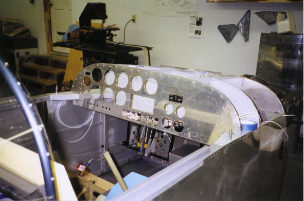
 I used a software package called "Panel Planner" to layout the panel. After much trial and error this is the basic layout I decided upon. The decision process was not an easy one. I wanted a conventional looking panel using aircraft style instruments as much as possible. I finally ended up with about 20 versions of the panel and could not make up my mind. So...I printed each panel (letter size) and pinned them on the walls of my shop. After staring at them for weeks on end I grabbed the one I wanted and printed out a full size color version along with a full size template Then it was only a matter of transferring the dimentions from the template to the panel and cutting it out.
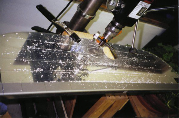 Lacking any better means of cutting holes, I again trust the hole cutting to my trusty fly cutter. I measured the face of each instrument and found that the standard 3-1/8" instrument is not so standard. The tach was larger than 3.125 and Navaid's gyro was closer to 3". Each hole was cut the proper size the the instrument that goes in it. As i write this I realize that this was not such a good idea if I replace a crapped out gyro with a different manufacture's. It may not fit.
 All holes are cut. The hard part was indexing the mounting holes on the center of the instrument holes. I did not get them perfect so I had to use pan head screws instead of countersunk screws. Oh Well!
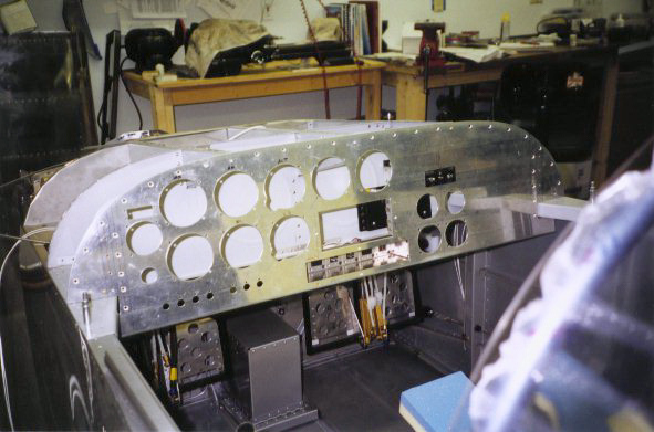 A view of the panel cutouts from the pilots side.
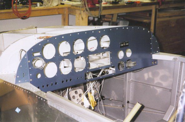 This is the first attemp of three at painting the panel. The chosen color was in spray cans and just as I finished the can sputtered. Try two was just as dismal. Finally I bought real paint and used my spray gun. My hat is off to you guys that can get a good paint job using spray bombs.
 This is early on in the installation of switches and wires. The wire count doubled as the job progressed. I used Electric Bob's basic wiring diagram with some Zilik mods here and there. Circut protection is by automotive blade fuses with one 5 amp breaker utilized for alternator over voltage protection.
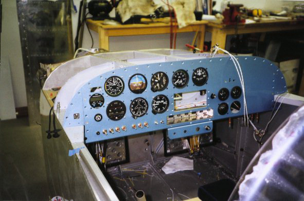 Saturday morning arrived and the panel and support wiring is almost done. After installing the radios and Michell gauges in their trays it was time to "Smoke Test" the system. Every thing worked as planned and all the smoke was kept inside the wires. This picture is before I installed the radios and engine instruments.