
Here are a few more pictures taken during construction of the fuselage of my RV-6A.
Click on the thumbnails for larger pictures.
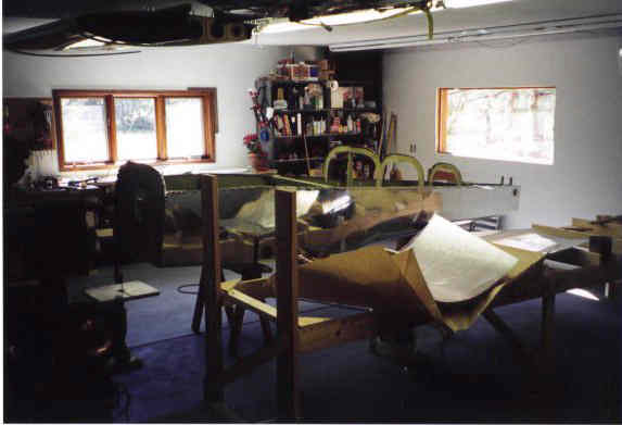 After what seemed like years of drilling and riveting the fuselage is removed from the jig and placed upright on saw horses. I called my wife down to the basement and with her help was able to lift the fuselage clear of the jig and set it on two saw horses. Once one the horsed, we flipped it over and took this picture. At this stage it weighs around 125 lbs.
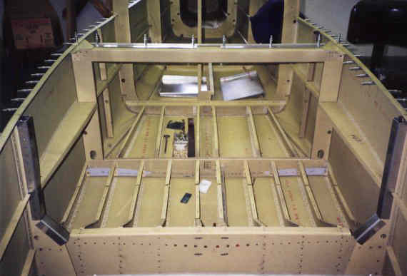 This is looking aft from the firewall. What a fine metal canoe I have constructed. This view shows the main bulkhead (f-604, rear spar carry through (f-605) and the main and baggage floor ribs.
 Installation of the floor and baggage side walls. The outer floor skins are riveted to the seat and baggage ribs while the center strip (white in this picture) is attached using #8 screws and platenuts. This will allow for installation and inspection of the elevator's forward push pull tube.
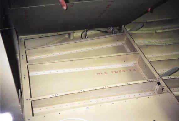 This is a view of the structure under the baggage floor just before final riveting of the floor skins.
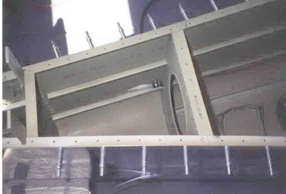
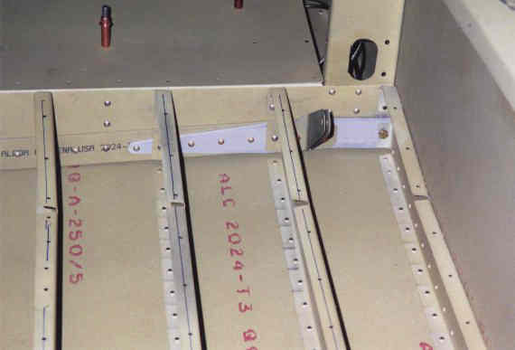 This shows the F-605 rear spar carry through. the F605-c doubler plate (Grey) extends out past the fuselage side and captures the rear wing spar with a single AN-5 bolt. Also shown here is the lap belt attach points.
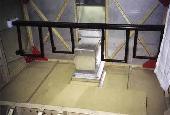
 Here I am installing the manual flap controls. The curved piece has indents for 0, 20 and 40 degree flap settings.
 The rudder pedal mounting, sans brake pedals. Battery box is in the center.
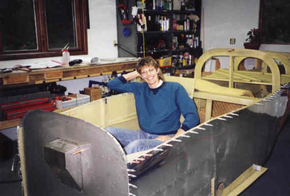 Carolyn sits in the plane for the first time.
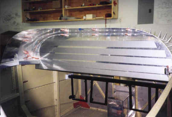
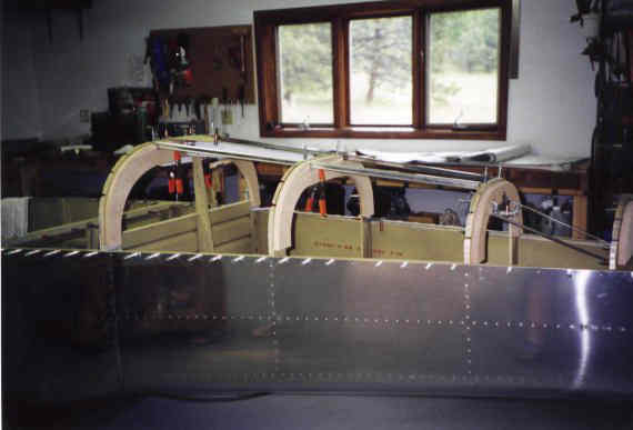 After taking turns sitting in the "Cockpit" and making airplane noises, it is time to get back to work. Here we are fitting the J-stringers for the turtle deck. The lower portion of the rear baggage wall is installed to keep the fuselage sides the proper distance apart. Plywood stiffeners were cut and clecoed in place to help keep the upper portions of the bulkheads straight while fitting and drilling the turtle deck skins.
 This is fuselage exit point for the rudder cables. Make the slot in the skins as long as possible so that the plastic tube is kept as straight as possible. The cable is a great saw, and straight runs limits it's cutting ability.
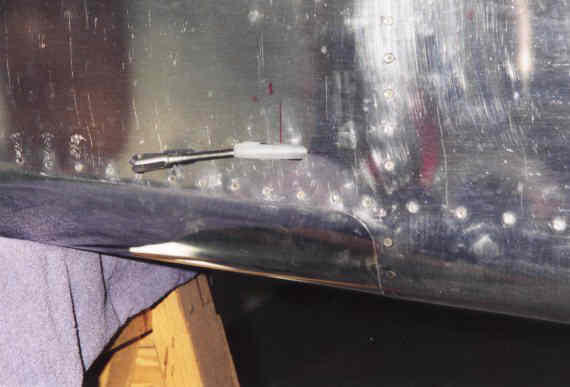
 Here is an inside shot of the cable sleeve anchor. As per plans, an adel clamp is attached with a #8 screw to the skin and keeps the plastic tube from moving fore and aft. I have been told that if you use the cable farings from Avery's, that they will hold the tube. I have both. Better to be safe, than sorry.
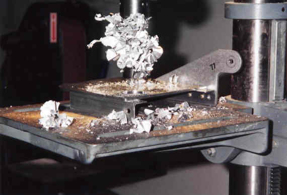 I ordered the dual brake system long after the fuselage and the new brake pedals came with 1" lightening holes. Of course I had already assemble the pilots pedals and now needed to drill the 1" holes in the pedals. I found that a forstner bit works wonders for cutting holes in 1/8" aluminum.
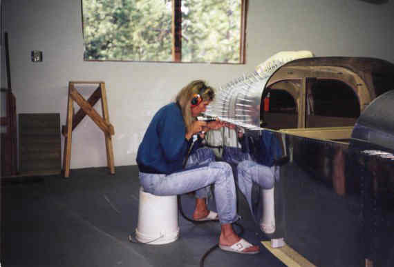 Carolyn got tired of waiting for more riveting and wanted to try her hand at drilling again. Here she is drilling the aft top skins to the main longeron. Note the OSHA approved safety shoes.
 Fitting the instrument panel on the slider is a slow process. I first made a cardboard template that sort of fit then transferred this to the panel. Progressive trimming finally brought it to the point you see here.
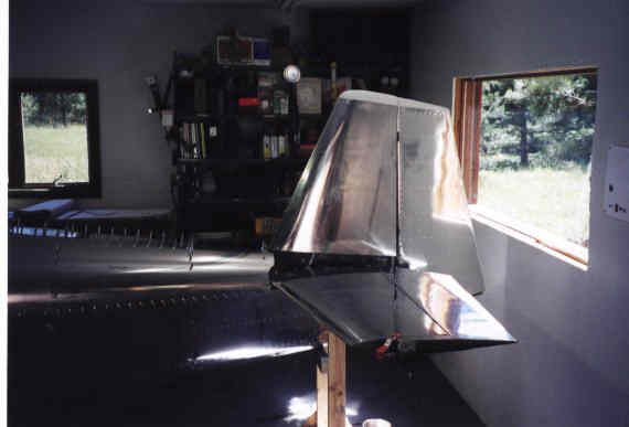 The empenage is finally fitted to the fuselage. Shims were needed for the vertical stab front spar.
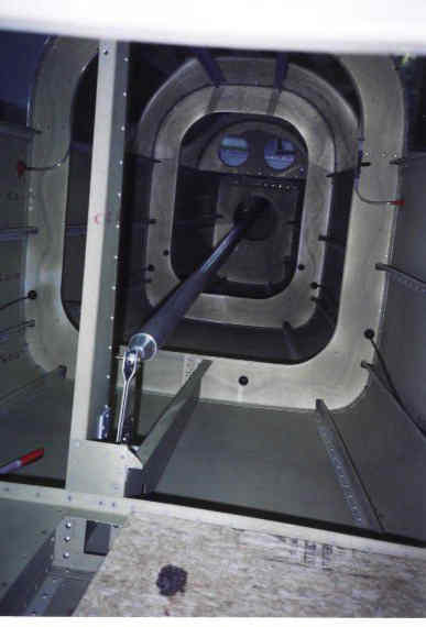 A look aft in the tail cone. The big tube is the elevator push-pull tube. A plywood sheet is used to protect the baggage floor from dropped tools. The forward push-pull tube has not been installed at this time.
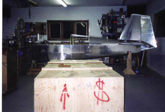 The finish kit arrives just in time. The finish kit ready fuselage is in the background.